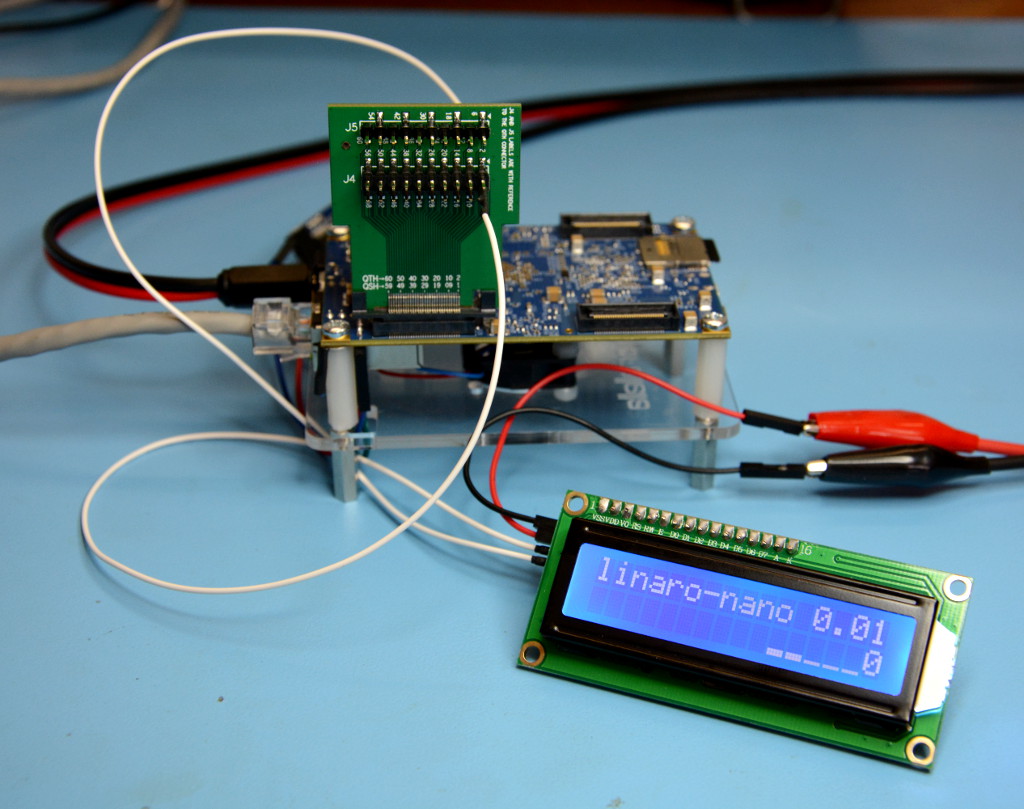
Hooking up an LCD to display real-time system information.
This post takes a look at how you can access the Parallella I2C bus via a breakout board, use it to interface a 16 character x 2 line LCD, and then drive this via the LCDproc software. Although there are many other types of display that could be interfaced via I2C — with some including additional features such as push buttons also — and other software that could be used to drive them.
Samtec connector breakout
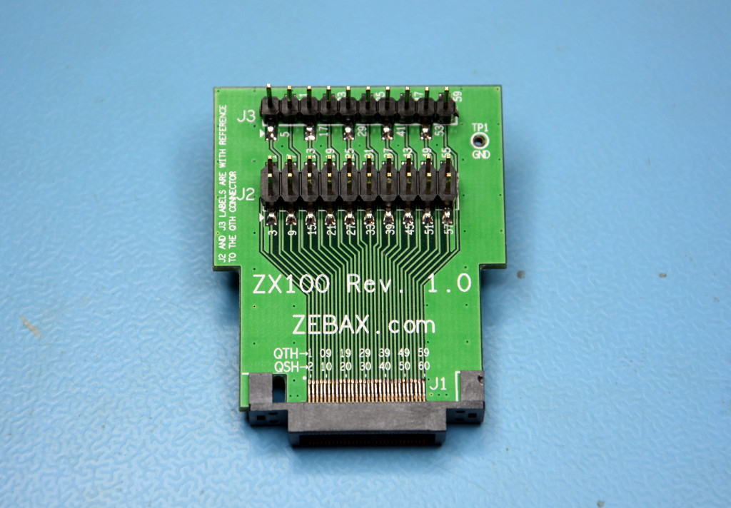
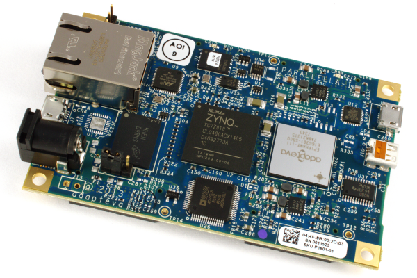
The Parallella has four Samtec “basic blade and beam headers” for expansion, which are designated BSH-030. The mating connector is BTH-030 and Zebax produce a board that breaks this out to 0.1” pitch headers, the ZX131-BTH030.
Note that although the board pictured above has QTH/QSH markings, this is presumably a generic PCB and breakout boards that are actually fitted with QTH series connector are incompatible!
HD44780 display with I2C
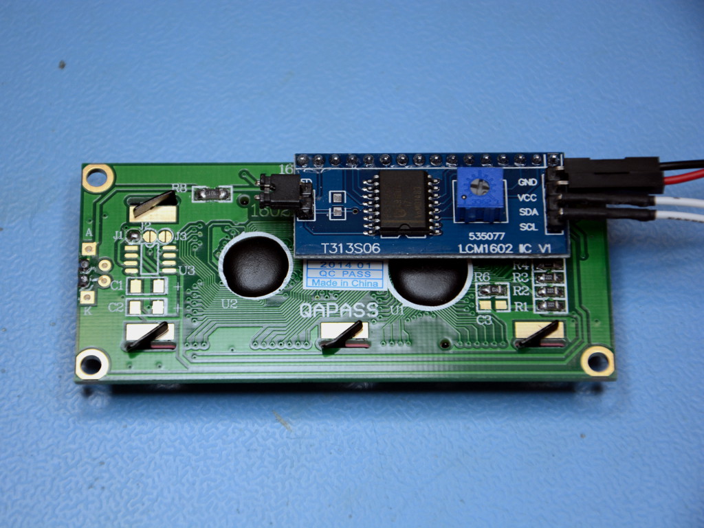
The LCD used here has a Hitachi HD44780 controller — which is particularly common and has great software support — and a PCF8574 I2C I/O expander which allows it to be driven using only 2 wires. 16×2 modules such as this can be picked up on eBay for as little $5-10.
Wiring up
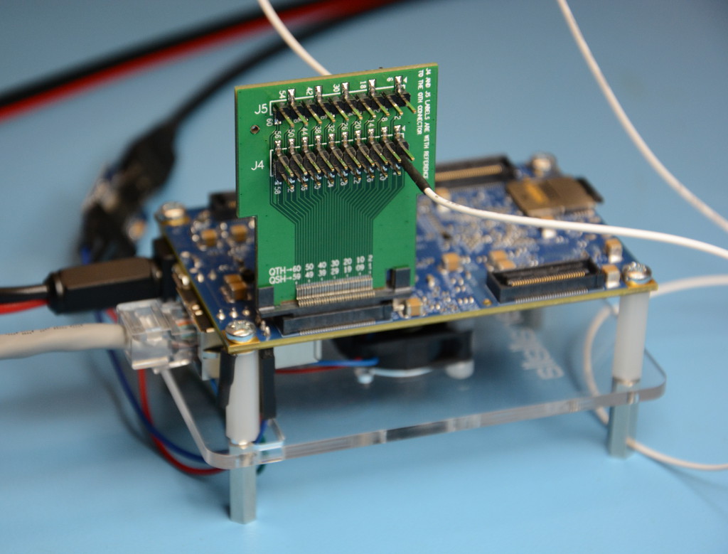
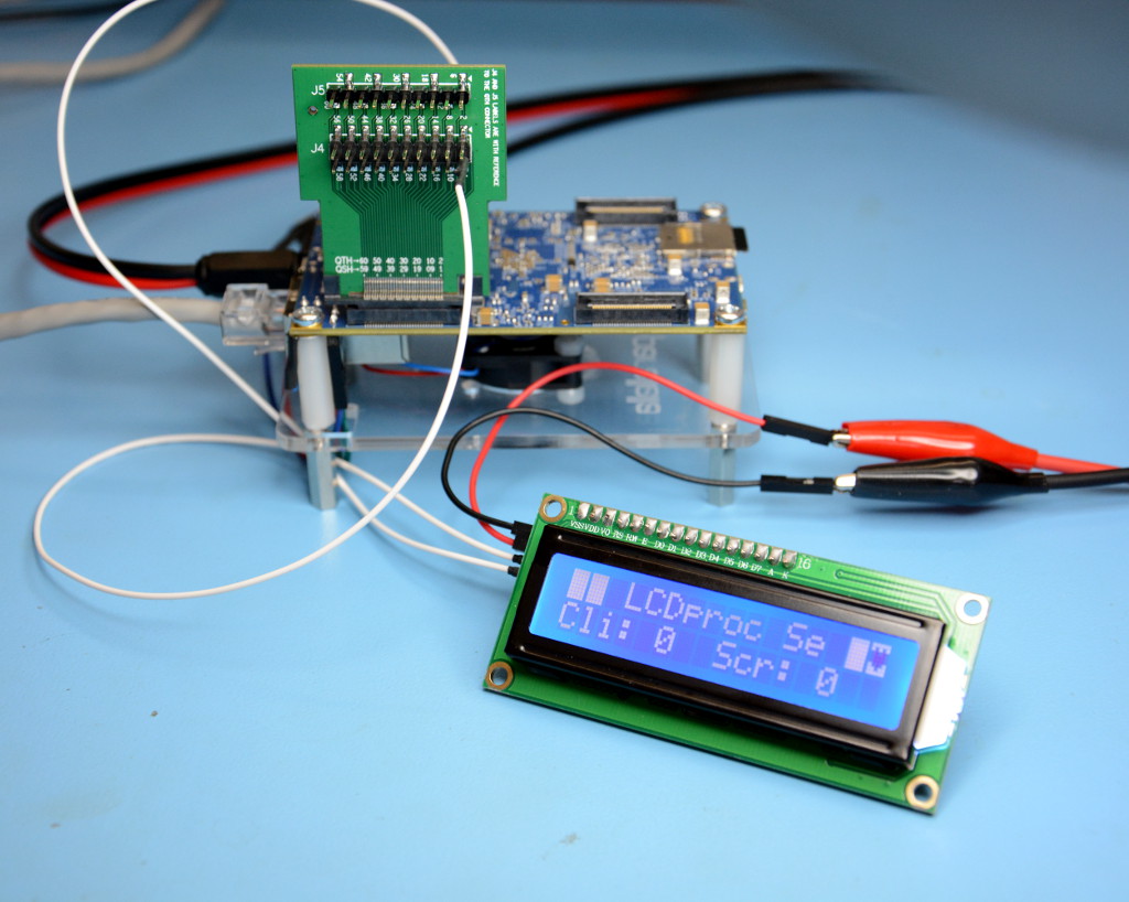
I2C is present on the PEC_POWER connector, which is the one closest to the Ethernet socket. The bus has two bidirectional lines, SCL and SDA, and these are on pins 3 and 4 respectively. Wires are run from these to those marked SCL and SDA on the display module.
The LCD module needs to be provided with a 5v supply and this can be found on PEC_POWER pins 1 &2, or alternatively can be taken via the Parallella mounting hole pads.
Note that connections should be made with power to the Parallella removed, and they should be checked and re-checked before power is applied. Errors may result in permanent damage!
For the PEC_POWER complete pinout see the Parallella Reference Manual.
Probing I2C
A handy set of utilities called I2CTools are used to probe the I2C bus. These can be installed with:
$ sudo apt-get install i2c-tools
To scan the bus for devices enter:
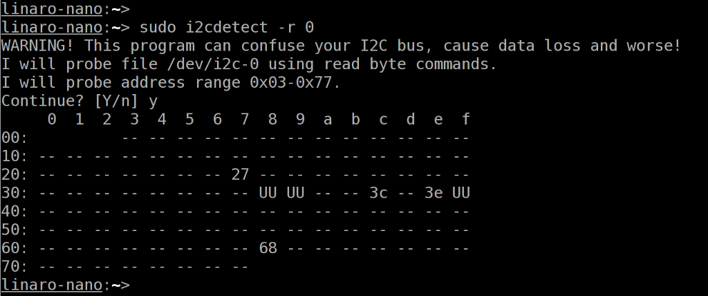
$ sudo i2cdetect -r 0
The vendor of the display I bought stated that it was configured for address 0x20. However, as can be seen above there is no device at that address, and it appeared at 0x27 instead.
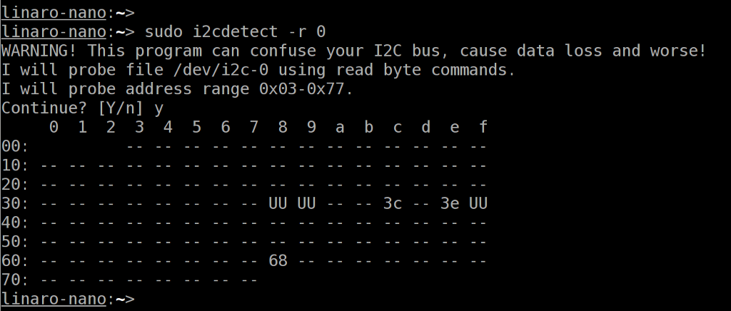
The output from a scan without the display or any other external devices attached can be seen below.
Parallella on-board I2C devices include things such as power management ICs. Those which are currently being used by a driver are marked UU. Attempting to write to on-board devices is strongly discouraged unless you know precisely what you are doing.
Installing LCDproc
The Ubuntu distribution provides a build of LCDproc which can be installed via apt-get. However, the stock hd44780-i2c driver assumes that the Hitachi controller is wired to the I2C port expander in the manner described in the documentation. Many are not, including the one I purchased, and using the package from the repository just causes garbage to be displayed and the backlight to flicker.
Fortunately, the changes required were found in a discussion thread on Sourceforge, and are minimal and it’s mostly a matter of changing pin assignments for the port expander. Suitably patched binary packages are available for download:
These can be installed with:
$ sudo dpkg -i lcdproc_0.5.5-2_armhf.deb lcdproc-extra-drivers_0.5.5-2_armhf.deb
Note that the patch in the above linked discussion was for a slightly older version of LCDproc, but I’ve generated a patch for 0.5.5-2 for those who prefer to build from source.
Configuring LCDd
LCDproc is built around a client-server model and the main part, the server daemon, is called LCDd. The configuration file for this is:
/etc/LCDd.conf
The key changes that need to be made are:
- Driver: set this to “hd44780”.
- HD44780 driver section: delete the default configuration and add the I2C example.
- Set the port address in the above section as appropriate, e.g. in my case 0x27.
Once this has been done restart LCDd:
$ sudo service LCDd restart
At this point the display should burst into life and display the driver’s built-in welcome message, followed by a screen which shows that 0 clients are connected.
Configuring lcdproc
LCDd clients connect over a TCP connection, the protocol is pretty simple and the display can even be updated via telnet, which is great for debugging.
A client called lcdproc is included which provides system status information. The configuration for this is held in:
/etc/lcdproc.conf
In there you can configure which system information you would like to be displayed and can specify a remote instance of LCDd should you wish.
To start the client:
$ lcdproc
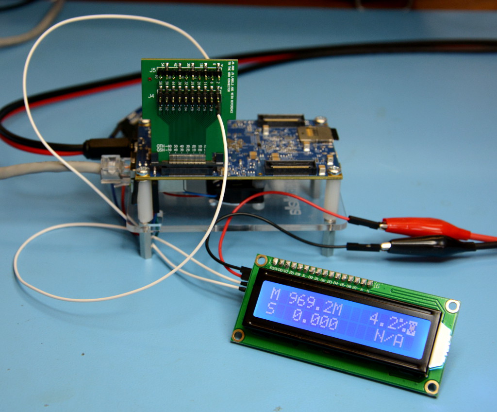
This will then fork to the background and the display should be updated to show things such as CPU and memory utilisation.

Other clients and client libraries are also available.
— Andrew
Hi Andrew
.
Any reason you can’t use pin 1 or 2 as the 5V supply for the display?
Thank you,
Errol
@Errol Not that I can see, no, and thanks for spotting this error — duly updated! I’d started out powering the display from direct leads to the PSU and then when I looked on PEC_POWER I think I must have been looking at all the rails on the opposite end of it and blind to 1 & 2.