Power the Parallella
Three ways to power the Parallella
1. Via the barrel connector on the board (J12)
2. Via the Micro USB connector next to the barrel connector (J7)
3. Via the mounting hole pads

Power Supply Options
Via the barrel connector on the board (J12)
This is the most commonly used method and the preferred option in most cases.
Via the Micro USB connector next to the barrel connector (J7)
The Micro USB connector next to the barrel connector can be used for powering the board, but should be used with extreme caution. USB power supplies are generally designed for charging applications and will rarely deliver sufficient current to power the Parallella board — even when they claim to be rated at 2A!
USB power will typically only power the Parallella with minimum activity and no peripherals.
To use the USB power connector move Jumper J14 from pins 1 and 2, to pins 2 and 3.
Note that no attempt should be made to power the board via the Micro USB connector at the front, next to the Micro HDMI connector!
Power via the mounting hole pads
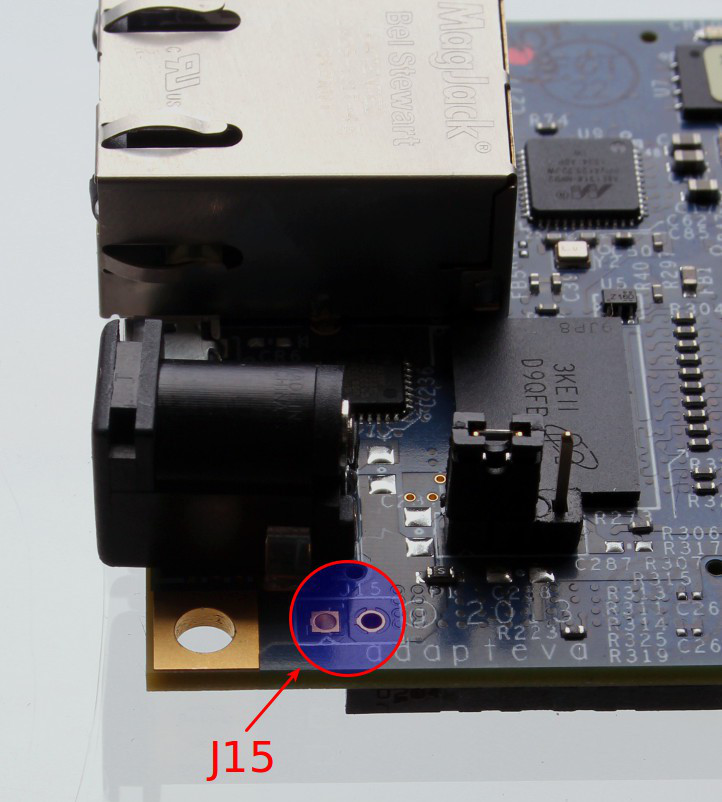
Three pads are grounded and the fourth, next to the barrel connector, can be a positive (+5VDC) if jumper J15 is added.
If the jumper J15 is fitted this will connect the Parallella’s 5V rail to the mounting hole pad that is adjacent to the power connector. The other three mounting hole pads are permanently connected to GND. This can be used to:
- Supply power to the board via the mounting hole pads;
- Power the board via the barrel connector and take power from the mounting hole pads.
A typical use of this feature is to take power for a cooling fan from the mounting hole pads.
J15 is located next to the power connector.

To fit the jumper:
- Cut around 6mm of solid core hook-up wire and bend this into a U shape, with the two ends 3mm apart.
- Insert this into J15, but note that it may not drop all the way in as there is a Samtec connector directly under one of the pads.
- Solder the link in place from the top side of the board.
Powering a cluster via a single PSU
With J15 fitted a cluster may be powered via a single power supply and the mounting hole pads.
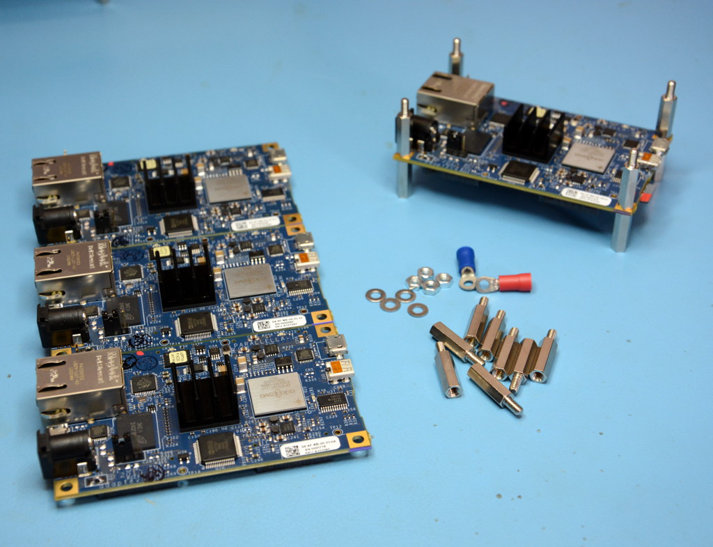
To assemble a stack of Parallella boards that are powered this way you need:
- Nickel plated male-female M3 hex spacers (stand-offs) with a 15mm body and 6mm stud
- 4x M3 nuts and 4x M3 washers
- 2x M3 crimp/solder tags
- Suitably rated wire
It is also advisable to have a non-conductive base onto which to mount the stack or, better still, a suitable enclosure.
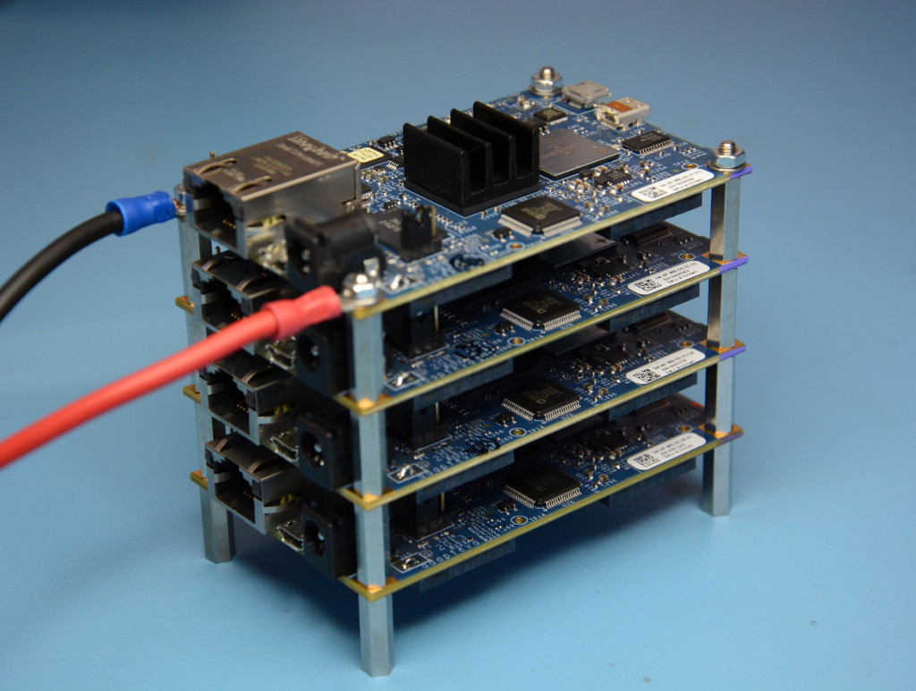
The cluster is assembled by sandwiching boards between metal stand-offs, with the stubs pointing upwards.
Tags are used to attach cables to the top studs, with a steel washer and nut screwed down onto each one.
Fixings should be secured “finger tight” and then gently tightened with a small spanner (5mm for the stand-offs and 5.5mm for the nuts). Care should be taken to not crush the PCBs and fixings just need to be tight enough to ensure a good electrical contact.
Note:
- This has only been tested with stacks of up to 8x boards and larger clusters should be split into multiple stacks of 8x boards or less.
- The cable used should be rated appropriately, e.g. a minimum of 8A for 4x boards and 16A for 8x boards.
- Zynq heatsinks should be oriented as shown above and a fan used to blow air across the long side of the stack and its entire height.
- Since the metal stand-offs are live care must be exercised with any metallic objects near the cluster while it is powered up!
- The stack must be placed on a non-conductive surface, and if it is mounted inside a plastic enclosure it is recommended that it be affixed to the enclosure with nylon screws and/or nylon stand-offs used at the bottom of the stack.
Powering a cluster with multiple PSUs
A cluster may be powered via multiple power supplies.
When using a power supply for each board:
- the power supplies should be plugged into a common power strip
J15 must not be fitted AND metal stand-offs used or else damage may occur!
Power Supply Requirements
- The Parallella board requires a high quality 5V DC regulated power supply rated at 2A output, with a 5.5mm OD / 2.1mm ID center positive polarity barrel plug.
- Poor quality and insufficiently rated power supplies are one of the most common causes of failure.
- Permanent damage may result from use with a supply >5V, that has an unregulated or AC output or a reverse-polarity connector!
Downloads
Parallella Reference Manual
Parallella Schematic
Epiphany Architecture Reference Manual
Epiphany SDK Reference Manual
Epiphany III 16-core Chip Product
Epiphany IV 64-core Chip Product