Construct Parallella Case
1. Remove the masking
2. Attach white mounting brackets
3. Mount the Parallella board
4. Insert the FacePlates
5. Mount the top panel
6. Attach the side panels

Instructions
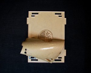
Step 1. Remove the masking
Start in a corner and peel off the masking.
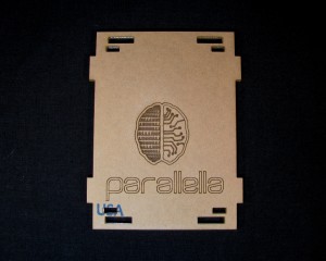
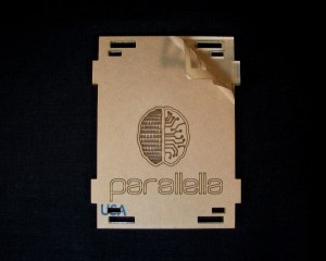
To remove the masking from the Logo, you can either use a fingernail or an exacto knife.
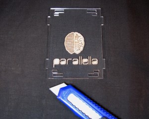
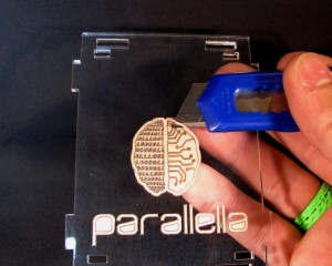
To remove the masking from the binary section of the logo, simply rub it off with your thumb.
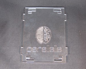
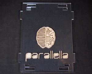
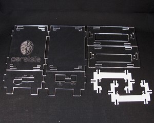
All the parts should look like this.
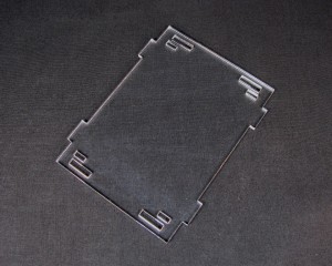
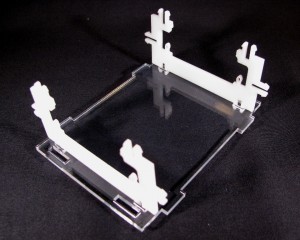
Step 2: Attach White Mounting Brackets
Take the two mounting brackets and snap them into the smaller slots on the bottom panel
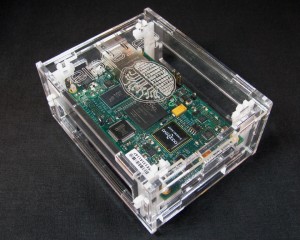
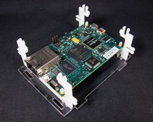
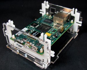
Step 3: Mount the Parallella Board
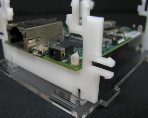
Slide the Parallella board through the mounting brackets and then push down near the PCB mounting nubs to lock the board in place.
Step 4: Insert the FacePlates
Take the Ethernet/USB/power faceplate and get it in the correct orientation as shown here.
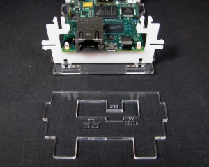
Now insert the two tabs into the the slots on the bottom panel at a slight angle to clear the Ethernet port.
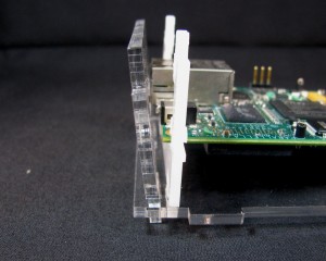
Once clear of the Ethernet port, push the faceplate into a vertical position.
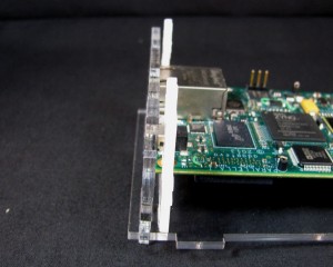
Repeat with the other faceplate.
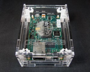
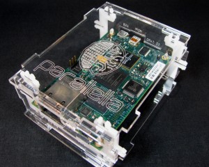
Step 5: Mount the Top Panel
Take the top panel and mount it with the Parallella logo over the Ethernet port.
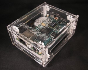
Step 6: Attach the Side Panels
Take the side panels and mount them so that the large slot is vertically centered on the Parallella Board
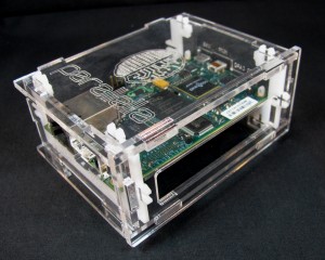
Congratulations!
You have successively assembled your Parallella enclosure.